
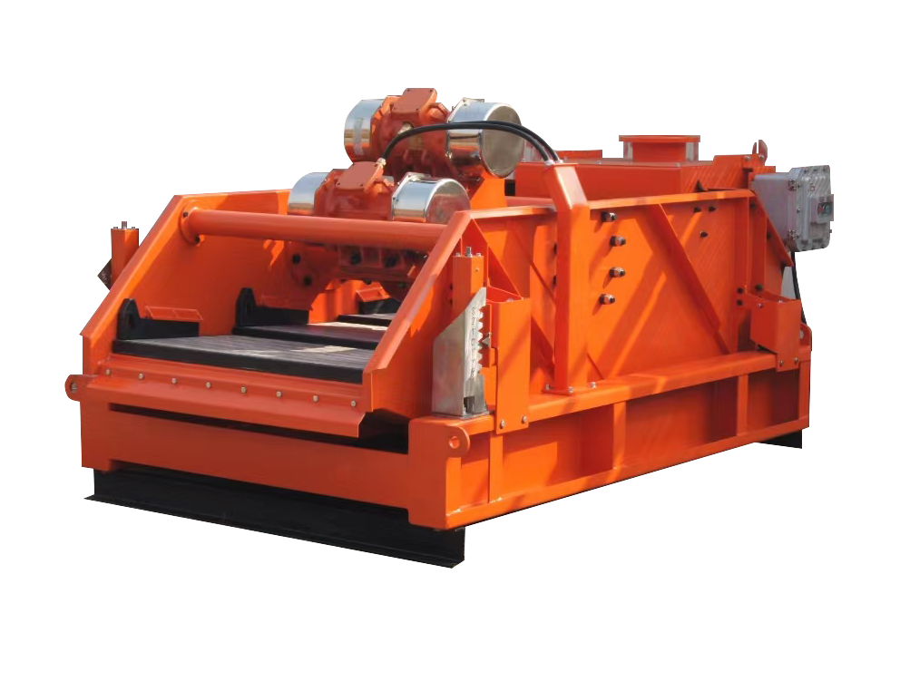


Drilling fluid shale shaker is the most used solid control equipment in the process of oil drilling mud treatment.
Drilling fluid shale shaker is the most used solid control equipment in the process of oil drilling mud treatment. Therefore, the selected drilling fluid shale shaker should have the advantages of high vibration strength, large screening area, adjustable screen box angle and compact structure, etc. The drilling fluid shale shaker plays a decisive role in the whole mud purification recycle system. At present, drilling fluid shale shaker is widely used in oil drilling, non-excavation horizontal directional crossing, coal bed methane drilling, shale gas drilling, river sludge environmental protection and other mud purification treatment fields.
It is the key equipment in the solids control equipment, which is responsible for cleaning a large amount of drill cuttings, controlling the solids content, reducing the workload of the lower level solids control equipment, and providing the lower level solids control equipment with drilling fluid to meet the treatment requirements. The drilling process requires the drilling fluid shale shaker to remove as much harmful solids as possible and to recover as much drilling fluid as possible. If the drilling fluid shale shaker fails, the next level of solids control equipment will be overloaded or even unable to operate normally, resulting in excessive solids content in the drilling fluid, making the drilling fluid performance worse and seriously affecting drilling safety and drilling speed. In order to improve the performance of the drilling fluid shale shaker, the structure has developed from single-shaft inertia shale shaker, double-shaft inertia shale shaker to energy-saving intelligent shale shaker. The structure of the shaker screen has experienced single-layer screen cloth, single-layer hooked edge screen cloth, double-layer hooked edge flat screen, corrugated conical screen to the mainstream of the composite frame multi-layer screen, the mesh of the screen from low mesh to high mesh screen development.

The screen box is the bearing part of the screen, the screen box is made of Q235 steel plate, its thickness is 8mm, using the box structure, it is made of side plate, cross support, strengthening plate and cross beam combination. As the screen box is supported by the side plate, the side plate bears the weight of the material and the screen box, and transmits the excitation force to the various parts of the screen box, and in order to strengthen the stiffness of the side plate, [12 channel steel is used on both sides of the side plate for reinforcement. The crossbeam is welded with double [12 channel steel and reinforcement plate of 10mm thickness.
The shaker screen is an important part for removing solid and recovering drilling fluid. The size of solid particles that can be removed by the shale shaker depends entirely on the size of the screen mesh. The shale shaker adopts stainless steel wedge-shaped slit screen mesh, the screen gap is 0.6mm, the external dimension is 1400×780mm, the area of screen surface is 1.1m2, in order to ensure the reliability of the screen surface, the method of fixing the screen surface also has a great influence on the capacity, this design adopts bolt compression. The bottom surface of the screen box is welded with six Φ48×4mm seamless steel pipes and the screen plate is bolted to it, which meets the strength requirement and saves the material; there is vulcanized rubber pad on the bolt clamp seat, which can avoid wear and tear and is not easy to damage the screen.
The outer box is welded with steel plate of 4mm thickness, and the inner part of water is processed with perforated plate of 2.5mm thickness, this structure has good mud buffering effect and can separate large grains of sand and debris.
Vibration damping device:
Adopt 4 high-strength spiral compression springs, with good stability, good damping effect and low noise. Damping springs are used to support the screen box and exciter, to ensure that the screen box has enough space for vibration, while assisting the screen box to achieve the required vibration, and buffer and reduce the dynamic load transmitted to the base and drilling fluid tank.
Base:
The base is all made of [12 channel steel welded to support the above parts.
Drilling fluid shale shaker is based on the eccentric force of the vibrating motor, through the excitation beam to produce linear motion, which drives the reciprocating motion of the whole screen box along the Y-axis direction. The particles are ejected and fall back under the vibration of the screen surface, so that the material moves forward continuously during the vibration of the screen surface, and the ejection and fall of the material have impact on the screen surface, resulting in the separation of particles smaller than the screen hole. At the same time, the mud on the screen surface is thrown up along the Y-axis direction, and then moves forward when it falls freely, so that it is constantly thrown up and down to make the mud move forward, and the mud liquid leaks into the mud pool through the screen, while the solid particles in the mud that are larger than the mesh of the screen are screened out, thus playing a role in the purification of the mud liquid.
1.Rotational speed(RPM)
2.Amplitude (mm) The two factors add up to the vibration strength G-Force, for example, 3.5g means the vibration strength is 3.5 back degrees of gravitational acceleration.
The size of the vibration strength determines the performance of the screening machine (throughput, screening efficiency)
During the drilling process, when the drilling fluid returns to the wellhead through the borehole with the rock chips, it enters the logging tank and manifold through the elevated tank, and flows into the shale shaker. Solid-liquid separation is a process, the initial flow of drilling fluid to the shale shaker screen can not be immediately separated, but while a small part of the screen, most of the liquid phase first along the surface of the screen immediately separated, and the screen surface to form a drilling fluid layer, drilling fluid layer with the separation process and increasingly thin, until a certain location on the screen surface liquid phase termination.
The location of the liquid phase termination is generally called the liquid phase termination line. After crossing the termination line, the solid phase particles continue to advance until they leave the shale shaker. When the drilling fluid shale shaker works normally, the liquid phase termination line is located at 2/3 to 3/4 of the effective length of the last screen, i.e. the drilling fluid spreads over 2/3 to 3/4 of the last screen. The sieving process includes the liquid phase penetration and the movement of the solid phase on the screen. The solid phase is an irregularly shaped and sized rock chip or chip mass, while the drilling fluid is a fluid with specific variability. The solid phase particles are immersed in the drilling fluid and remain as wet particles surrounded by the drilling fluid after separation. Therefore, the structure and parameters of the shale shaker and screen mesh, the performance of the drilling fluid, and the installation of the vibrating screen will directly affect the screening process and the effectiveness of the shale shaker.
In order to ensure the proper solid-liquid separation of drilling fluid on the screen, the particles should be thrown on the surface of the screen in order to achieve both a high throughput and a high chip discharge rate. In the process of throwing, the particles are transported to the discharge port in the shape of a projectile. If the throwing index is small, when the solid particles are in a submerged state, the transport speed is too slow, which will easily block the screen and reduce the processing capacity, and even cause slurry running and drilling fluid loss. When the solid phase particles are separated out, too slow transportation speed will increase the chance of small particles penetrating the screen, and even cause solid phase particles to accumulate on the screen, which will cause the screen to be destroyed early due to overload. The throwing index should not be too large, as long as the solid phase particles can overcome the adhesion between it and drilling fluid and separate out, too large will increase the collision of particles falling on the screen, resulting in the probability of more tiny particles through the screen, but also intensify the wear and tear of the screen, reduce the life of the screen, but also put forward higher requirements for the strength of the shale shaker.
The stratigraphic conditions vary greatly from region to region, and the characteristics of the rock chips also vary greatly, so there are many differences in the performance and parameters of the drilling fluid used. When selecting a shale shaker, the vibrating screen amplitude, throwing index, trajectory, throwing angle, motor installation position, spring installation position and vibration frequency should be fully considered according to the geographic formation chip situation, drilling fluid performance and drilling parameters to select the matching shale shaker. For the area with complex stratum and large changes in the nature of rock chips, we can consider using frequency conversion and adjustable excitation force linear and planar elliptical double-track shale shaker to select the suitable frequency, excitation force, throwing angle and trajectory according to the nature of rock chips in the stratum. Generally, in the case of large rock chip particles and high specific gravity, the excitation force is high and the vibration frequency is low; in the case of small and fragile rock chip particles, the excitation force is low and the vibration frequency is high, and the matching parameters are selected.
Poor rigidity of the base support and unreliable fixation will cause distortion of the trajectory during the use of the shale shaker, and the base of the shale shaker should be installed on a rigid base with good rigidity and reliable fixation during installation.
When maintenance the shale shaker and replace the damping spring, must replace the same performance, elasticity of the spring, forbidden to mix the old and new spring. When replacing the excitation motor, the motor of the same model and similar performance should be replaced, otherwise it is difficult for the shale shaker to achieve resonance and affect the use effect.
Solidscontrolworld-High Quality Shale Shaker Screen Manufacturer has more than 13 years of experience in drilling solid control field; we can choose the right type of shale shaker for you; cost-effective shale shaker will not let you down; you can trust our service, contact us now!
Shale shakers are adapted to separate large solids from fluids in drilling & mining. They are the first phase of solids & mud treatment in oil & gas mining and drilling. They reduce the level of solids content & facilitate other stages by giving lower levels of solids control equipment with drilling fluids to advance the treatment needs.
Shale shakers are critical solid control equipment in cleaning & separating drill cuttings. They are vital in solids cleaning, mud treatment & removing foreign compounds/materials.
Main Features of Shales Shakers
-Sieve Box
-Shale Shaker Screens
-Mud Feed Box
-Power Device
-Vibration Damping Device
| Model | ABZS 104 | ABZS 103 | ABZS 70-3P | ABZS 103K | ABZS 85-2P |
|---|---|---|---|---|---|
| Capacity | ≤ 150m3 / h ( 660 GPM) | ≤ 120m3 / h ( 528 GPM) | ≤ 120m3 / h ( 528 GPM) | ≤ 120 m3 / h ( 528 GPM) | ≤ 80 m3 / h ( 352 GPM) |
| Rated Motors Output | 1.865kw ( 2.5hp) x2 ( Martin ) | 1.5kw(2 .0 hp)x2(OLI) | 1.72kw (2 .3hp)x2 (OLI) | 1 .5 kw ( 2 .0 h p ) x2 ( OLI ) | 1 .0 kw ( 1 .3 5 h p ) x2 ( OLI ) |
| Output Force | ≤ 8 .5 Gs | ≤ 8 .0 Gs | ≤ 7 .5 Gs | ≤ 8 .0 Gs | ≤ 7 .0 Gs |
| Operating Temperature | 3 0 °C ( 8 6 °F ) | 3 0 °C ( 8 6 °F ) | 3 0 °C ( 8 6 °F ) | 3 0 °C ( 8 6 °F ) | 3 0 °C ( 8 6 °F ) |
| Design Range | - 4 0 - 5 0 °C (- 4 0 - 1 2 2 °F ) | - 4 0 - 5 0 °C (- 4 0 - 1 2 2 °F ) | - 4 0 - 5 0 °C (- 4 0 - 1 2 2 °F ) | - 4 0 - 5 0 °C (- 4 0 - 1 2 2 °F ) | - 4 0 - 5 0 °C (- 4 0 - 1 2 2 °F ) |
| Noise Date | 7 5 - 8 5 d BA | 7 5 - 8 5 d BA | 7 5 - 8 5 d BA | 7 5 - 8 5 d BA | 7 5 - 8 5 d BA |
| Deck Adjustment | - 1 °~ + 5 ° | - 1 °~ + 5 ° | - 1 °~ + 5 ° | - 1 °~ + 5 ° | - 1 °~ + 3 ° |
| Screen Material | Composite frame / Metal frame | Composite Metal Frame | Metal Frame | Stainless Steel/ polyurethane | Metal Frame |
| Screen Size | 5 8 5 x1 1 6 5 m m | 5 8 5 x1 1 6 5 m m | 7 0 0 x1 2 5 0 m m | 5 8 5 x1 1 6 5 m m | 8 5 0 x1 2 5 0 m m |
| Screen Qty | 4 p c s | 3 p c s | 3 p c s | 3 p c s | 2 p c s |
| Filtering Area | 2 .7 3 m 2 ( 3 0 ft 2 ) | 2 .1 m 2 ( 2 3 .5 ft 2 ) | 2 .6 3 m 2 ( 2 9 .2 ft 2 ) | 2 .1 m 2 ( 2 9 .2 ft 2 ) | 2 .1 m 2 ( 2 3 .5 ft 2 ) |
| Weightt | 1 4 8 0 kg s | 1 3 2 0 kg s | 1 4 0 0 kg s | 1 3 9 5 kg s | 1 2 5 0 kg s |
| Dimention | 2 9 5 0 x1 6 9 0 x1 4 2 0 | 2 3 7 0 X1 6 9 0 X1 4 2 0 | 2 8 7 0 x1 7 7 2 x1 4 0 0 | 2 3 7 0 x1 6 9 0 x1 4 2 0 | 2 4 4 0 x1 7 7 2 x1 4 0 0 |
| Voltage | 2 2 0 - 2 4 0 V/ 5 0 Hz , 3 8 0 - 4 1 5 V/ 5 0 Hz , 4 4 0 - 4 8 0 V/ 6 0 Hz , 5 7 5 - 6 0 0 V/ 6 0 Hz | ||||
| Approval | UL/ ATEX/ BV/ IADC/ J AS - ANZ IS O 9 0 0 1 :2 0 1 5 / CE | ||||
| Test Conditions for these parameters: Mud Density:1.2 g/cm3, Mud Viscosity:45s, Screen: 40 mesh | |||||
Shale Shaker: The First Line of Defense in Drilling Fluid Solids Control
Mud Pump Q&A: Answers to Operators’ Most Frequent Questions
How to Choose a Suitable drilling fluids Shale Shaker
© Copyright 2025 SolidsControlWorld, All Rights Reserved.
WhatsApp us
